6.
Motor and gearbox combinations
D.C. motors are constructed to operate continuously within a range of speeds near their no-load speed. This range of speeds is generally too high for most applications. In order to reduce this speed, a full range of geared motors is available, each with a series of gear ratios to suit most speed requirements.The complete range is suitable for a wide variety of applications.
Gearbox characteristics:
Our gearboxes have been designed for optimum performance and for maximum life under normal operating conditions.Their main characteristic is the capacity to withstand maximum design torque with continuous duty.The range of gearboxes shown in this catalogue can operate with maximum torque of 0.5 to 6 N.m for long time periods. All values previously stated are for standard products in normal operating conditions, as specified.In certain cases, these values may be increased if a shorter life is required.Please consult our Sales Office for further information.Every gearbox has a torque limit, which is the breaking torque If this torque is applied to the gearbox, it will cause severe damage.
Gearbox construction
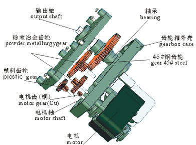
The module,depth and material of Gears are calculated according to the stress of gear at each step. By life test of motor to produce the motor with low noise and enough life time. Gearbox can be assembled with DC motors, DC brushless motors and shade pole motors.
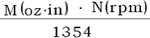
Selection of a geared motor:A geared motor is selected according to the required usable power output.
useableP(W)=
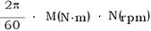
useableP(W)=
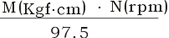
useableP(W)=
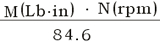
useableP(W)=
Selecting the reduction gear ratio:Two selection criteria may be applied.
* The first criterion concerns the required speed output of the reduction gear only. It is adequate for most applications and is easy to apply. Given that :

N1= required speed of geared motor B1=basic nominal speed of motor
* The second criterion concerns the required usable power output of the motor. The rotational speed of the motor is given by :
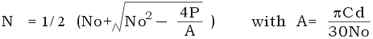
N = speed of motor(rpm) No = no loadspeed of motor(rpm)
P = required output power(W) Cd = start-up torque of motor(Nm)
this gives the equation:

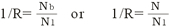
In order to avoid using numbers less than 1 where the reduction ratio is concerned, the value 1/R is employed.
Due to the fact that it is always a reduction gear and not a "ultiplier" gear, there should be no ambiguity concerning the number used.
7.
Product technology introduction
1).1.Generally reducer with single pair of gears transmission, parallel shaft structure and ordinary gear train is called gear reducer. Mostly straight gear and slanting gear are used in mini gear reducers. The reduction ratio of mini gear reducer is generally designed within range 1:200 except of extremely mini reducers.
2.)Planetary gear reducer is a transmission structure of multi pairs of gears Transmission and dynamic gear train, spanning wide range of reduction ratio up to max. reduction ratio 1:1730. The planetary gear reducer has the character of small figure, light weight, heavy load, high efficiency and stable running. Compared with gear reducer, it can save 30%---50% both of volume and weight, specially suitable fro application requesting big reduction ratio and compact structure. Now for the reason that the speed of DC motor is hardly up to 1000 per minute but DC motor of relatively light rotating speed can lower speed and enhance torque after being assembled together with planetary gear reducer of small reduction ratio, Planetary gear reducer is frequently equipped in application requesting high rotating speed.
3.)The main character of worm reducer is of crossed-axis transmission. 90 degree angle between output shafts of motor and reducer, stable running,low noise and self locking function. Its shortage is low efficiency.
4.)Rated load torque: output torque of motor at status of rated voltage, rated frequency and rated speed (of the diagram). The general calculation formular:Rated load torque=rated torque of motor X reduction ratio X transmission efficiency of reducer,Restrained by the maximum torque of reducer of big reduction motor,the maximum torque value is equivalent to the rated one. if the calculated value of rated load torque is bigger than the maximum torque.
5)Transmission efficiency of reducer: Torque efficiency of motor equipped with reducer, usually expressed in percentage. It is influenced by friction of bearing and gear, and condition of lubricating grease. Generally the transmission efficiency is 90%, transmission is 95% after the first gear train, and 81% after the second gear train. Bigger reduction ration requires motor gear trains and leads to lower transmission efficiency.The transmission efficiency of planetary gear reducer is much higher, generally its efficiency of one gear train.
8.
Torque Caculation method of induction geared motors.
Torque Caculation method of speed control motor and geared motors:
1. Motor without gearbox, after adjust speed, output torque is "Mn",output speed is "n", motor speed at 1300 rpm, torque is "M1300",when the motor turn 90 degree, output toque is "M90",the formula is Mn=(M1300-M90)/1200X(n-90)+M90.
.2. Motor after geared reduction, the torque is "Mi", ratio is "i" ,the running efficiency is "η",the formula Mn X i X η
Note: running efficiency
a、reduction ratio 1:4-1:18, η ≈81%
b、reduction ratio 1:25-1:36,η ≈73%
c、reduction ratio above 1:50,η ≈66% |
|
If the motor is used beyond the above conditions,please inform us. |
|
